
Installation and
Operations Manual
MODEL 5496
Intelligent Power Module
P/N 151276:E1 ECN: 10-484
Document 151276
08/12/10 Rev:
E1

151276 i
Contents
Section 1
Overview ...................................................................................................................................................... 1-1
1.1 5496 Description ...................................................................................................................................... 1-1
1.2 Agency Requirements .............................................................................................................................. 1-1
1.3 About This Manual .................................................................................................................................. 1-1
1.4 How to Contact Silent Knight ..................................................................................................................1-1
Section 2
Before You Begin Installing ............................................................................................... 2-1
2.1 What’s in the Box? ................................................................................................................................... 2-1
2.2 Environmental Specifications .................................................................................................................. 2-1
2.3 Preventing Water Damage ....................................................................................................................... 2-1
2.4 5496 Board and Terminal Strip Description ............................................................................................ 2-2
2.5 Earth Fault Resistance .............................................................................................................................. 2-3
2.6 Calculating Current Draw and Standby Battery ...................................................................................... 2-4
2.6.1 Worksheet Requirements .................................................................................................................. 2-4
Filling in the Current Draw Worksheet ......................................................................................... 2-4
2.6.1.1 Maximum Battery Standby Load ........................................................................................... 2-4
2.6.2 Current Draw Worksheet .................................................................................................................. 2-5
2.6.3 Wire Routing ..................................................................................................................................... 2-6
Section 3
Hardware Installation .................................................................................................................. 3-1
3.1 AC Power ................................................................................................................................................. 3-1
3.2 Battery Connection .................................................................................................................................. 3-2
3.3 Connecting the 5496 to the FACP ........................................................................................................... 3-3
3.3.1 Setting the Device ID ........................................................................................................................ 3-4
3.4 Notification Appliance Wiring ................................................................................................................. 3-5
3.4.1 Class A Supervised Wiring ............................................................................................................... 3-5
Class A Output Notification Circuits ............................................................................................ 3-5
3.4.2 Class B Supervised Wiring ............................................................................................................... 3-6
Class B Output Notification Circuits ............................................................................................ 3-6
3.4.3 Releasing Operations ........................................................................................................................3-6
3.4.4 Auxiliary Power Configuration ........................................................................................................ 3-7
3.4.4.1 Door Holder Power ................................................................................................................ 3-8
3.4.4.2 Constant Power ...................................................................................................................... 3-8
3.4.4.3 Resettable Power .................................................................................................................... 3-8
Model 5496 Intelligent Power Module Installation and Operation Manual
ii 151276
Appendix A
Compatible Devices
..................................................................................................................... A-1
Silent Knight Fire Product Warranty and Return Policy
Manufacturer Warranties and Limitation of Liability

151276 1-1
Section 1
Overview
1.1 5496 Description
The Model 5496 Intelligent Power Module provides additional power and notification circuits
to a Silent Knight addressable FACP. The 5496 can power all IntelliKnight compatible
notification appliances and auxiliary power modules.
The 5496 is capable of performing single or dual interlocking operations for pre-action and
deluge releasing systems. See Section 8.6 of FACP installation manual.
The 5496 has four output circuits that can be configured as notification or auxiliary power
circuits. Outputs are rated 3.0 A (6.0 A total for each 5496).
The 5496 is optically isolated, providing ground loop isolation and transient protection.
The 5496 provides configuration options that eliminate the need for sychronization modules
when using AMSECO, Faraday, Gentex, System Sensor, or Wheelock synchronization
appliances.
1.2 Agency Requirements
The 5496 has the same requirements as the main control panel. These requirements are listed
in Silent Knight addressable FACP Installation Manuals. Silent Knight Addressable FACP
Installation Manuals can be found on Silent Knight’s web site at www.silentknight.com.
1.3 About This Manual
This manual covers installation of 5496 hardware. Software configuration information is
contained in a Silent Knight addressable FACP Installation Manuals. Silent Knight
Addressable FACP Installation Manuals can be found on Silent Knight’s web site at
www.silentknight.com.
1.4 How to Contact Silent Knight
If you have a question or encounter a problem not covered in this manual, contact Silent
Knight Technical Support at 800-446-6444.
To order parts, contact Silent Knight Sales at 800-328-0103 or (203) 484-7161.
Model 5496 Intelligent Power Module Installation and Operation Manual
1-2 151276

151276 2-1
Section 2
Before You Begin Installing
2.1 What’s in the Box?
The Model 5496 ships with the following hardware:
• A cabinet with all hardware assembled
• Two keys for the 5496 front door
• Ten 4.7K ohm end-of-line resistors
Note: For UL installations Model 7628 4.7k end-of-line resistor (ordered separately) must be used.
• A battery wiring harness and jumper to wire batteries in series
2.2 Environmental Specifications
It is important to protect the 5496 control panel from water. To prevent water damage, the
following conditions should be AVOIDED when installing the units:
• Do not mount directly on exterior walls, especially masonry walls (condensation)
• Do not mount directly on exterior walls below grade (condensation)
• Protect from plumbing leaks
• Protect from splash caused by sprinkler system inspection ports
• Do not mount in areas with humidity-generating equipment (such as dryers, production
machinery)
When selecting a location to mount the 5496, the unit should be mounted where it will NOT
be exposed to temperatures outside the range of 0°C-49°C (32°F-120°F) or humidity outside
the range of 10%-93% at 30°C (86°F) noncondensing.
2.3 Preventing Water Damage
Water damage to the fire system can be caused by moisture entering the cabinet through the
conduits. Conduits that are installed to enter the top of the cabinet are most likely to cause
water problems. Installers should take reasonable precautions to prevent water from entering
the cabinet. Water damage is not covered under warranty.
Model 5496 Intelligent Power Module Installation and Operation Manual
2-2 151276
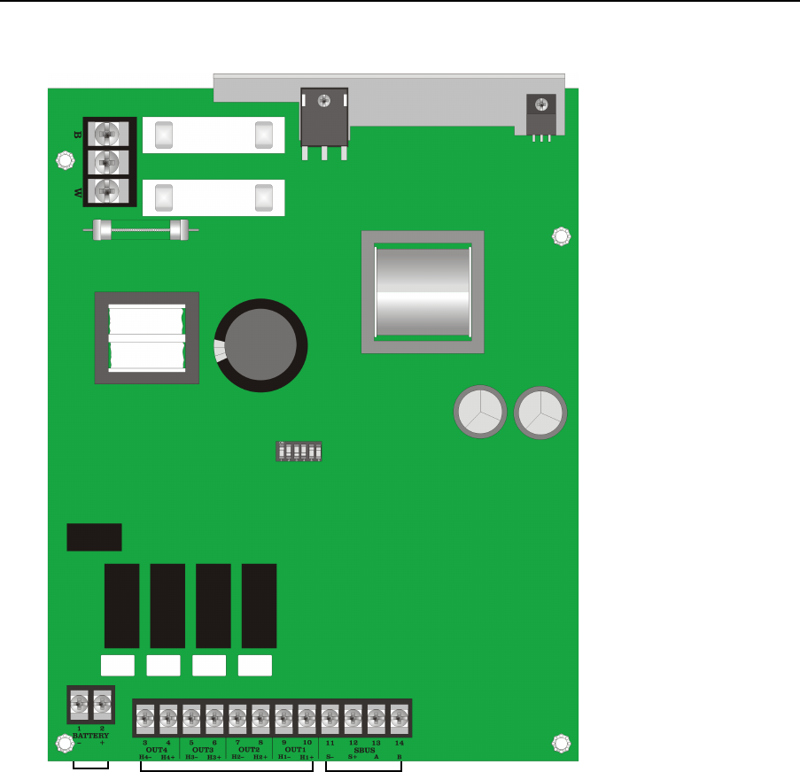
2.4 5496 Board and Terminal Strip Description
Figure 2-1 shows the 5496 circuit board including location of terminals and the dipswitch for
setting the module ID.
Figure 2-1 The 5496 Board Layout
Dipswitches for
Setting ID
To AC
Regulated
SBUS Module
Connections
Battery
Connections
Output Circuits
All Circuits
Supervised Power
limited, except
Battery and AC
which are
supervised
non-power limited.
Before You Begin Installing
151276 2-3
Table 2-1 describes the 5496 connections and provides electrical ratings where appropriate.
* Regulated/special application when used for releasing.
2.5 Earth Fault Resistance
Table 2-2 lists the earth fault resistance detection for each applicable terminal on the FACP.
Table 2-1: Terminal Strip Description and Electrical Ratings
Terminal # and Label
Description
Rating
Voltage Current
B AC input (hot) 120 VAC, 60 Hz 2.7 A
Earth ground N/A N/A
W AC input (neutral) 120 VAC, 60 Hz 2.7 A
1-
Battery Battery 24 VDC 0.75 A
2+
3 -
I/O 4* Output circuit 24 VDC
3.0 A
Notification Circuits
4 +
5-
I/O 3* Output circuit 24 VDC
3.0 A
Notification Circuits
6+
7 -
I/O 2* Output circuit 24 VDC
3.0 A
Notification Circuits
8 +
9-
I/O 1* Output circuit 24 VDC
3.0 A
Notification Circuits
10 +
11 -
SBUS
SBUS power 24 VDC 1.0 A
12 +
13 A
SBUS communication 5 VDC 100 mA
14 B
Table 2-2: Earth Fault Resistance Values by Terminal
Function
Terminal
Number
Terminal Label
Value
(in ohms)
Battery
1-
BATTERY
0
2+ 0
Notification Appliance Circuit 4
3H4-
OUT4
0
4 H4+ 0
Notification Appliance Circuit 3
5H3-
OUT3
0
6 H3+ 0
Notification Appliance Circuit 2
7H2-
OUT2
0
8 H2+ 0
Notification Appliance Circuit 1
9H1-
OUT1
0
10 H1+ 0

Model 5496 Intelligent Power Module Installation and Operation Manual
2-4 151276
2.6 Calculating Current Draw and Standby Battery
This section is for helping you determine the current draw and standby battery needs for your
installation.
2.6.1 Worksheet Requirements
Follow the steps below to determine 5496 current draw and standby battery requirements.
Filling in the Current Draw Worksheet
Refer Table 2-4 in Section 2.6.2 to complete the following steps.
1. Add up the current draw for all auxiliary devices and record in the table at Line B.
2. Add up all notification appliance loads and record in the table at Line C.
3. For notification appliances and auxiliary devices not mentioned in the manual, refer to the
device manual for the current ratings.
4. Make sure that the total alarm current you calculated, including current for the panel itself,
does not exceed 6.0 A. This is the maximum alarm current allowable.
5. Complete the remaining instructions in Table 2-4 to determine battery size requirements.
2.6.1.1 Maximum Battery Standby Load
Table 2-3 shows the maximum battery standby load for the 5496 based on 24 and 60 hours of
standby. The standby load calculations of line J in the Current Draw Calculation Worksheet
(Table 2-4) must be less than the number shown in Table 2-3 for the battery size used and
standby hours required.
Note: 33 max battery size for FM (Factory Mutual) installations
Table 2-3: Maximum Battery Standby Load
Rechargeable
Battery Size
Max. Load for 24 hrs. Standby,
5 mins. Alarm
*Max. Load for 60 hrs. Standby, 5
mins. Alarm
7 AH 270 mA 105 mA
12 AH 475 mA 190 mA
18 AH 685 mA 270 mA
35 AH 1370 mA 540 mA
* Required for NFPA 72 Auxiliary Protected Fire Alarm systems for Fire Alarm Service (City Box) and
Remote Station Protected Fire Alarm systems (Polarity Reversal) and Digital Alarm Communicator/
Transmitter (DACT).

Before You Begin Installing
151276 2-5
2.6.2 Current Draw Worksheet
For each 5496 in the installation, use this worksheet to determine current requirements during
alarm/battery standby operation. (Copy this page if additional space is required.)
Table 2-4: Current Draw Calculation Worksheet
Device
Number of
Devices
Current per Device
Standby
Current
Alarm
Current
For each device use this formula: This column X This column = Current per number of devices.
5496 Intelligent Power Module
(Current draw from battery)
1
Standby: 40 mA 40 mA
Alarm: 160 mA 160 mA
A
5496 Current 40 mA 160 mA
Auxiliary Devices Refer to device manual for current ratings.
Alarm/Standby mA mA mA
Alarm/Standby mA mA mA
Alarm/Standby mA mA mA
Alarm/Standby mA mA mA
B
Auxiliary Devices Current mA mA
Notification appliances Refer to device manual for current ratings.
Alarm: mA 0 mA mA
Alarm: mA 0 mA mA
Alarm: mA 0 mA mA
Alarm: mA 0 mA mA
C
Notification Appliances Current
0 mA mA
D
Total current ratings of all devices in system (line A + line B + line C)
mA mA
E
Total current ratings converted to amperes (line D x .001):
AA
F
Number of standby hours (24 or 60 for NFPA 72, Chapter 1, 1-5.2.5).
H
G
Multiply lines E and F. Total standby AH
AH
H
Alarm sounding period in hours.
(For example, 5 minutes = .0833 hours.)
H
I
Multiply lines E and H. Total alarm AH
AH
J
Add lines G and I. Total standby and alarm AH
AH
Model 5496 Intelligent Power Module Installation and Operation Manual
2-6 151276
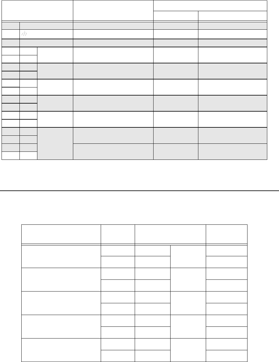
2.6.3 Wire Routing
You must follow power-limited wiring techniques, which include maintaining one-quarter
inch spacing between power-limited and non-power limited circuits and separating high and
low voltage circuits.
Figure 2-2 Wire Routing Example
5496 Board
To AC
Power
To Battery
To SBUS
Terminals
To NACs
151276 3-1
Section 3
Hardware Installation
5496 installation involves the following steps:
• Connect AC power (Section 3.1) and backup battery (Section 3.2).
• Make physical connection to a Silent Knight addressable FACP (see Section 3.3).
• Set an ID for the 5496 (Section 3.3.1).
• Make physical connection to any outputs that will be powered by this 5496. See Section
3.4 for notification appliance wiring information. Refer to Silent Knight addressable
FACP Installation Manuals for software configuration information and other information
about installing outputs. Silent Knight Addressable FACP Installation Manuals can be
found on Silent Knight’s web site at www.silentknight.com.
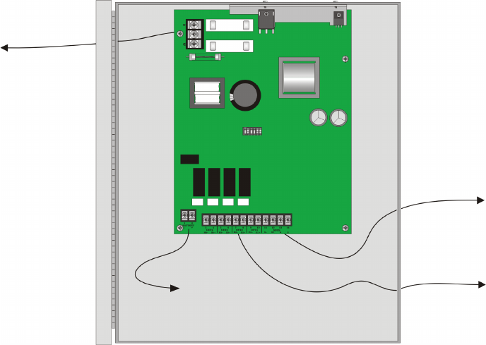
3.1 AC Power
At installation, connect the AC terminals to 120 VAC source as shown in Figure 3-1. It may
be necessary for a professional electrician to make this connection.
The AC terminals are rated as 120 VAC, 50 or 60 Hz, 2.5 A.
Figure 3-1 AC Power Connection
To AC
To 120 VAC
Power Source
Supervised
Non-power limited
Model 5496 Intelligent Power Module Installation and Operation Manual
3-2 151276
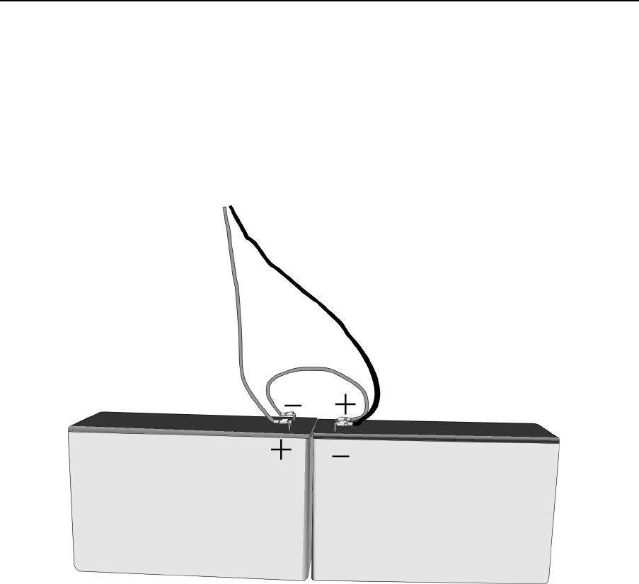
3.2 Battery Connection
The 5496 battery charge capacity is 7.0 AH not to exceed 35.0 AH. Use 12V batteries of the
same AH rating. It is recommended that you replace batteries every five years. Determine the
correct AH rating per your current load calculation (see Table 2-4).
Note: If you require the power of back up batteries that are too large for the 5496, you can use the RBB cabinet.
The RBB Remote Battery Box, holds batteries up to the 35 AH size. (Refer to P/N 151306 for RBB instal-
lation instructions.
Wire batteries in series to produce a 24-volt equivalent. Do not parallel batteries to increase
the AH rating.
Figure 3-2 Battery Connection
Red
To Panel
Black
UL Listed 12V BatteryUL Listed 12V Battery
Battery Jumper
(P/N 140694)
Shipped With 5496
Supervised
Non-Power Limited
Replace batteries every 5 years.
Gell Cell Gell Cell
Hardware Installation
151276 3-3
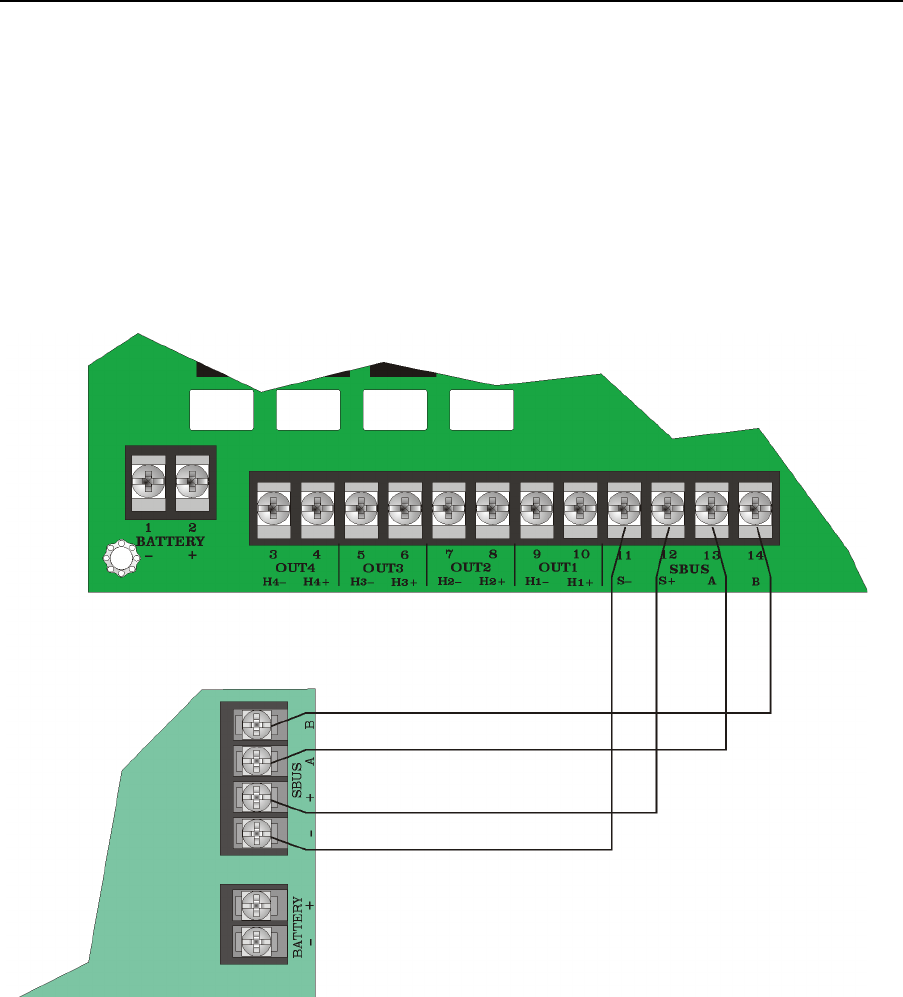
3.3 Connecting the 5496 to the FACP
1. Connect the 5496 to the appropriate SBUS. The 5496 is connected directly to a Silent
Knight addressable FACP.
2. Use the on-board dipswitch to assign an ID number to the 5496. (See Section 3.3.1) Figure
2-1 shows the location of the dipswitches on the 5496 board.
3. Configure the 5496 module by adding it to the system (through JumpStart or manually).
You can also assign a name to the module. These procedures are described in Silent
Knight addressable FACP Installation Manuals. Silent Knight Addressable FACP
Installation Manuals can be found on Silent Knight’s web site at www.silentknight.com.
Figure 3-3 Class B 5496 Connection to FACP
5820XL
(Main SBUS)
5496 Board
Supervised
Power Limited
Model 5496 Intelligent Power Module Installation and Operation Manual
3-4 151276
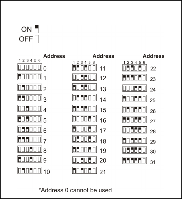
3.3.1 Setting the Device ID
All SBUS modules in the system must have a unique number (1-31) to identify them to the
FACP. Use the DIP switch on the 5496 board to set the module ID number. Figure 2-1 shows
the location of the dipswitch on the board. Figure 3-4 shows dipswitch setting and the
corresponding module ID numbers.
Figure 3-4 Possible Module Addresses
Hardware Installation
151276 3-5
3.4 Notification Appliance Wiring
Note: Not all devices can use the Sync feature. Be sure to check Table A-1 in Appendix A to ensure the device
you have chosen will work with this feature.
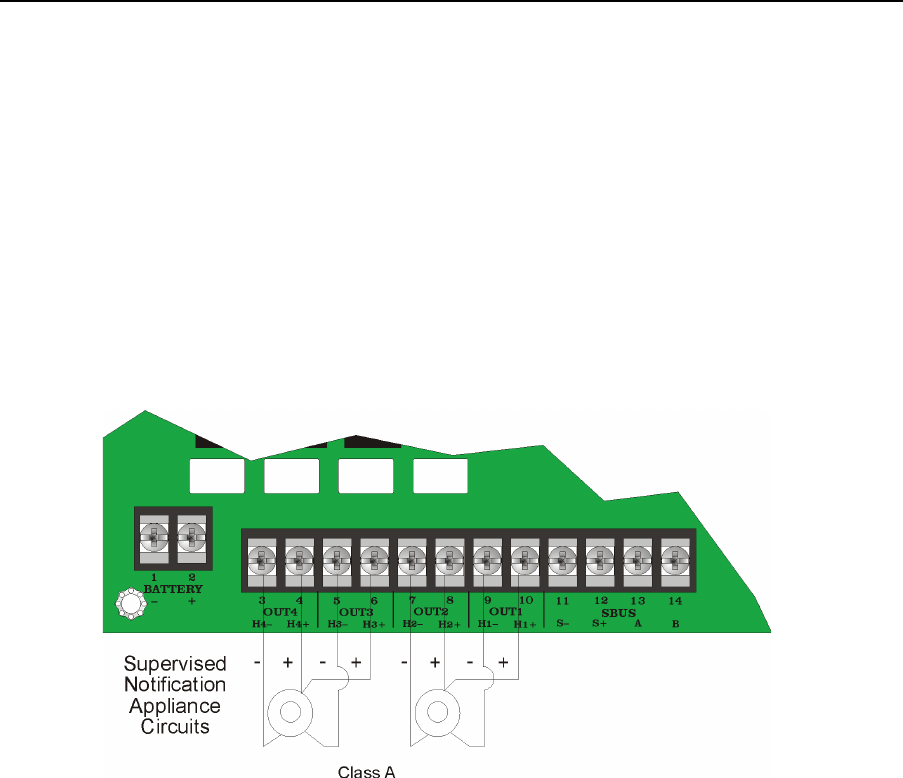
3.4.1 Class A Supervised Wiring
Figure 3-5 shows how to wire for Class A output supervision. Use in/out wiring methods for
proper supervision. Refer to Section 4 for notification appliances compatible with the 5496.
Class A Output Notification Circuits
The configuration shown in Figure 3-5 shows two, 3-amp devices wired as Class A circuits.
When you are using the outputs as Class A circuits, loop the wiring back to the corresponding
circuit pair. For Class A wiring, no external EOL is necessary since it is built into the 5496
board.
Figure 3-5 Class A Supervised Input/Output Connections
Power Limited
1.5max
Model 5496 Intelligent Power Module Installation and Operation Manual
3-6 151276
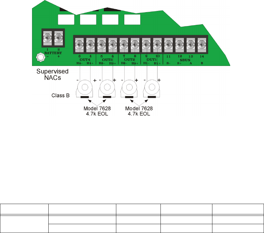
3.4.2 Class B Supervised Wiring
Figure 3-6 shows how to wire for Class B output supervision. Use in/out wiring methods for
proper supervision. Refer to Section 4 for notification appliances that must be used with the
5496.
Class B Output Notification Circuits
Figure 3-6 shows four, 1.5 amp devices wired as Class B circuits.
Place a 4.7k ohm EOL resistor (provided) at the end of each circuit to enable supervision
when using all outputs as Class B notification appliance circuits. The 4.7k EOLs must be
wired to the terminals whether or not you are using all output terminals.
Figure 3-6 Regulated Class B Supervised Input/Output Connections
3.4.3 Releasing Operations
Approved releasing solenoids are list in Table 3-1. Do not mix cross alarming zones with
smoke verification zones. There must be at least two automatic detection devices in each
protected space. Spacing must be reduced to 0.7 times the linear spacing in accordance with
NFPA 72.
Table 3-1: Approved Releasing Solenoids
Manufacturer Part Number Rating Current Freq
Asco T8210A107 24 VDC 3A max 0 Hz
8210G207 24 VDC 3A max 0 Hz
Power Limited
1.5max
Hardware Installation
151276 3-7
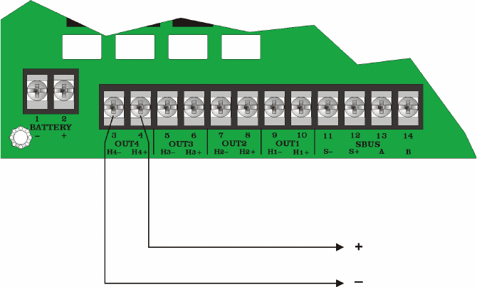
3.4.4 Auxiliary Power Configuration
Output circuits 1-4 on the control panel can be used as auxiliary power circuits. The three
types of auxiliary power available are:
• Door Holder (see Section 3.4.4.1 for description)
• Constant (see Section 3.4.4.2 for description)
• Resettable (see Section 3.4.4.3 for description)
Auxiliary power circuits are power limited. Each circuit can source up to 3A (total current for
all output circuits must not exceed 6 A).
To configure an output circuit as auxiliary power:
1. Wire the output circuit(s) that will be used for auxiliary power. See Figure 3-7 for location
of the output circuits.
2. Configure the auxiliary power output through programming for Door Holder, Constant or
Resettable power.
Figure 3-7 Output Circuits Used as Auxiliary Power
Power Limited
Supervised when used with the
Power Supervision Relay (PN160150)
Model 5496 Intelligent Power Module Installation and Operation Manual
3-8 151276
3.4.4.1 Door Holder Power
Door holder is intended for fire door applications. When there are no alarms in the system and
the panel has AC power, door holder circuits have 24-volt power present at their terminals.
Any alarm will cause power to discontinue. Power will be re-applied when the system is reset.
If AC power is off for more than 15 seconds the auxiliary door holder power will be
discontinued to conserve the battery backup power. When AC power is restored, power is
immediately restored to the door holder circuits.
3.4.4.2 Constant Power
Use constant power for applications that require a constant auxiliary power source. Power is
always present at Constant circuits.
3.4.4.3 Resettable Power
Resettable power is typically used to power beam detectors, flame detectors, and conventional
4-wire smoke detectors. For circuits selected as Resettable, 24-volt power is always present at
the terminals unless a system reset occurs. If a system reset occurs, power is removed from the
terminals for 30 seconds, then re-applied.

151276 A-1
Appendix A
Compatible Devices
For proper operation, you must use polarized devices with a Model 7628 4.7k ohm EOL
resistor on each circuit. All supervised notification appliances used with the IFP-FFT must be
polarized.
A.1 Notification Appliances
Note: Not all devices can use the Sync feature, be sure to check A.1 to ensure the device you have chosen will
work with this feature. This control is UL listed for single circuit synchronization.
Table A-1 below lists notification appliances compatible with the fire alarm control panel.
Appliances which can be synchronized indicate the type of sync available in the columns
marked Audio and/or Visual
Table A-1: Compatible Notification Appliances
Manufacturer Model Audio Visual Type
AMSECO
SH24W-153075 Horn/Strobe
SAD24-153075 Strobe
SAD24-75110 Strobe
SL24W-75110 Strobe
SL24C-3075110 Strobe
SLB24-75 Strobe
RSD24-153075 Strobe
RSD24-75110 Strobe
SH24W-75110 Horn/Strobe
SH24W-3075110 Horn/Strobe
SHB24-75 Horn/Strobe
SCM24W-153075 Chimes/Strobe
SCM24W-75110 Chimes/Strobe
SCM24C-3075110 Chimes/Strobe
SCM24C-177 Chimes/Strobe
H24W Horn
H24R Horn

Model 5496 Intelligent Power Module Installation and Operation Manual
A-2 151276
Faraday
446 Vibrating Bell
476 Vibrating Bell
477 Single Stroke Bell
2700 -M. -R, -T, -Y, -Z Strobe
2701 Series Strobe
2705 Series Strobe
2820 Snyc Temporal Horn/Strobe
2821 Snyc Temporal Horn/Strobe
2824 Horn Strobe
5333 Multi-Tone Horn)
5336 Multi-Tone Horn/Strobe
5337 Multi-Tone Horn/Strobe
5338 Multi-Tone Horn/Strobe
5343 Single Tone Horn/Strobe
5346 Electronic Horn with Strobe
5347 Electronic Horn with Strobe
5348 Single Tone Horn/Strobe
5373 8-Tone Horn/Strobe
6321 Sync Mini Horn/Strobe
6322 Mini Horn/Sync Strobe
6380 8-Tone Electronic Signal/Strobe
5376 8-Tone Horn/Strobe
5377 8-Tone Horn/Strobe
5378 8-Tone Horn/Strobe
5383 8-Tone Horn/Strobe with Sync Strobe
5386 8-Tone Horn/Strobe with Sync Strobe
5387 8-Tone Horn/Strobe with Sync Strobe
5388 8-Tone Horn/Strobe with Sync Strobe
5508 Single Gang Sync Strobe
5509 Strobe
Table A-1: Compatible Notification Appliances
Manufacturer Model Audio Visual Type

Compatible Devices
151276 A-3
Faraday
con’t
5510 Strobe
5511 Strobe
5512 Strobe
5516 Strobe
5517 Strobe
5518 Strobe
5519 Strobe
5521 4” Square Sync Strobe
5522 4” Square Sync Strobe
6120 Horn
6140 Horn
6223 Horn
6226 Horn/Strobe
6227 Horn/Strobe
6228 Horn/Strobe
6243 Electron-Mechanical Horn
6244 Electron-Mechanical Horn
6245 Electron-Mechanical Horn
6246 Electron-Mechanical Horn/Strobe
6247 Electron-Mechanical Horn/Strobe
6248 Electron-Mechanical Horn/Strobe
6300 Mini-Horn
6301 Mini-Horn
6302 Mini-Horn
6310 Mini-Horn/Strobe
6311 Mini-Horn/Strobe
6312 Mini-Horn/Strobe
6314 Series -M, -R, -T, -Y, -Z Strobe
6320 Sync Mini Horn/Strobe
Table A-1: Compatible Notification Appliances
Manufacturer Model Audio Visual Type

Model 5496 Intelligent Power Module Installation and Operation Manual
A-4 151276
FCI
S2415-FC Strobe
S241575-FC Strobe
S2430-FC Strobe
130-3117C Mini Horn
130-3147C Mini Horn
BLV-6 Vibrating Bell
BLV-10 Vibrating Bell
BLVCH Vibrating Chime
H12/24-FC Horn
H12/24W-FC Horn
H12/24K-FC Horn
HC12/24-FC Horn
HC12/24W-FC Horn
HC12/24K-FC Horn
P2415-FC Horn/Strobe
P2415W-FC Horn/Strobe
P2415K-FC Horn/Strobe
P241575-FC Horn/Strobe
P241575W-FC Horn/Strobe
P241575F-FC Horn/Strobe
P241575K-FC Horn/Strobe
P2430-FC Horn/Strobe
FCI
P2430W-FC Horn/Strobe
P2430K-FC Horn/Strobe
P2475-FC Horn/Strobe
P2475W-FC Horn/Strobe
P2475K-FC Horn/Strobe
P24110-FC Horn/Strobe
P24110W-FC Horn/Strobe
P24110K-FC Horn/Strobe
S2430W-FC Strobe
S2430K-FC Strobe
S2475-FC Strobe
S2475W-FC Strobe
S2475K-FC Strobe
S24110-FC Strobe
S24110W-FC Strobe
S24110K-FC Strobe
Federal Signal
450 Horn
VALS Horn/Strobe
Table A-1: Compatible Notification Appliances
Manufacturer Model Audio Visual Type

Compatible Devices
151276 A-5
Gentex
GEC-24-15 Horn/Strobes
GEC-24-30 Horn/Strobes
GEC-24-60 Horn/Strobes
GEC-24-75 Horn/Strobes
GEC-24-177 Horn/Strobes
GEC-24-110 Horn/Strobe
GEC-24-15/75 Horn/Strobe
GX91 MiniHorn Steady Tone
GX93 MiniHorn Temporal Tone
HG124 Horn
HS24-15 Horn/Strobe
HS24-30 Horn/Strobe
HS24-60 Horn/Strobe
HS24-75 Horn/Strobe
HS24-110 Horn/Strobe
HS24-1575 Horn/Strobe
GCC24 Multi Candella Horn/Strobe Ceiling Mount
GCCR24 Multi Candella Horn/Strobe Ceiling Mount
GCS24 Multi Candella Strobe Ceiling Mount
GCSR24 Multi Candella Strobe Ceiling Mount
GECR-24 Multi Candella Horn/Strobe
GES24-15 Strobes
GES24-30 Strobes
GES24-60 Strobes
GES24-75 Strobes
GES24-110 Strobes
GES24-15/75 Strobes
Gentex
con’t
GES24-177 Strobes
GES3-24 Multi Candella Strobe
GESR-24 Multi Candella Strobe
GEH-24 Horn
ST24-30 Strobe
ST24-60 Strobe
ST24-75 Strobe
ST24-110 Strobe
ST24-1575 Strobe
WGEC24-75W Weatherproof Horn/Strobe
WGES24-75W Weatherproof Strobe
WGMS-24-X Horn/Strobe
Table A-1: Compatible Notification Appliances
Manufacturer Model Audio Visual Type

Model 5496 Intelligent Power Module Installation and Operation Manual
A-6 151276
System Sensor
CHR Chime
CHW Chime
CHSR 2-Wire Chime/Strobe
CHSW 2-Wire Chime/Strobe
HR Horn
HW Horn
HRK Horn
P2R 2-Wire Horn/Strobe
P2R-P 2-Wire Horn/Strobe
PC2R 2-Wire Horn/Strobe
PC2R-P 2-Wire Horn/Strobe
P2RH 2-Wire Horn/Strobe High Candela
P2RH-P 2-Wire Horn/Strobe High Candela
PC2RH 2-Wire Horn/Strobe High Candela
PC2RH-P 2-Wire Horn/Strobe High Candela
P2W 2-Wire Horn/Strobe
P2W-P 2-Wire Horn/Strobe
PC2W 2-Wire Horn/Strobe
PC2W-P 2-Wire Horn/Strobe
P2WH 2-Wire Horn/Strobe High Candela
P2WH-P 2-Wire Horn/Strobe High Candela
PC2WH 2-Wire Horn/Strobe High Candela
PC2WH-P 2-Wire Horn/Strobe High Candela
P2RK 2-Wire Horn/Strobe
PC2RK 2-Wire Horn/Strobe
P2RHK 2-Wire Horn/Strobe High Candela
PC2RHK 2-Wire Horn/Strobe High Candela
P4R 4-Wire Horn/Strobe
PC4R 4-Wire Horn/Strobe
P4RH 4-Wire Horn/Strobe High Candela
P4W 4-Wire Horn/Strobe
Table A-1: Compatible Notification Appliances
Manufacturer Model Audio Visual Type

Compatible Devices
151276 A-7
System Sensor
con’t
PC4W 4-Wire Horn/Strobe
P4WH 4-Wire Horn/Strobe High Candela
PC4WH 4-Wire Horn/Strobe High Candela
P4RK 4-Wire Horn/Strobe
PC4RK 4-Wire Horn/Strobe
P4RHK 4-Wire Horn/Strobe High Candela
PC4RHK 4-Wire Horn/Strobe High Candela
PC4RH 4-Wire Horn/Strobe High Candela
SR Strobe
SR-P Strobe
SCR Strobe
SCR-P Strobe
SRH Strobe High Candela
SRH-P Strobe High Candela
SCRH Strobe High Candela
SCRH-P Strobe High Candela
SW Strobe
SW-P Strobe
SCW Strobe
SCW-P Strobe
SWH Strobe High Candela
SWH-P Strobe High Candela
SCWH Strobe High Candela
SCWH-P Strobe High Candela
SRK Strobe
SCRK Strobe
SRHK Strobe High Candela
SCRHK Strobe High Candela
Table A-1: Compatible Notification Appliances
Manufacturer Model Audio Visual Type

Model 5496 Intelligent Power Module Installation and Operation Manual
A-8 151276
Wheelock
AH-12 Horn
AH-24 Horn
AH-12WP Horn Weatherproof
AH-24WP Horn Weatherproof
AMT-241575W Multi-Tone Horn Strobe
AMT-24MCW Mutli-Tone Horn Strobe
AMT-241575W-NYC Multi-Tone Horn Strobe
AMT-12/24 Multi-tone Horn
AMT-12/24 NYC Multi-tone Horn
AS-121575W Horn/Strobe
NH-12/24 Horn
AS-241575W Horn/Strobe
AS-24MCC Horn/Strobe
AS-24MCCH Horn/Strobe
AS-24MCW Horn/Strobe
AS-24MCWH Horn/Strobe
ASWP-2475W Horn/Strobe Weatherproof
ASWP-2475C Horn/Strobe Weatherproof
ASWP-24MCWH Horn/Strobe
ASWP-24MCCH Horn/Strobe
CH-70 Chime
CH-90 Chime
CH70-241575W Chime/Strobe
CH70-24MCW Chime/Strobe
CH70-24MCWH Chime/Strobe
CH90-24MCC Chime/Strobe
Table A-1: Compatible Notification Appliances
Manufacturer Model Audio Visual Type

Compatible Devices
151276 A-9
Wheelock
con’t
CH90-24MCCH Chime/Strobe
HS-24 Horn
HS4-241575W Horn/Strobe
HS4-24MCW Horn/Strobe
HS4-24MCWH Horn/Strobe
HS4-24MCC Horn/Strobe
MIZ-24S Mini Horn Strobe
MT-121575W MultitoneHorn Strobe
MT-241575W Multitone Horn Strobe
MT-24MCW Multitone Horn Strobe
MTWP-2475W Multitone Horn Strobe
MTWP-2475C Multitone Horn Strobe
MTG-121575W Multitone Horn Strobe
MTR-121575W Multitone Horn Strobe
MTWPA-2475W Multitone Horn Strobe
MTWPB-2475W Multitone Horn Strobe
MTWPG-2475W Multitone Horn Strobe
MTWPR-2475W Multitone Horn Strobe
MTWPA-24MCCH Multitone Horn Strobe
ZNH Horn
NS-121575W Horn/Strobe
NS-241575W Horn/Strobe
NS-24MCW Horn/Strobe
NS-24MCC Horn/Strobe
NS-24MCCH Horn/Strobe
ZNS-MCW Horn/Strobe
ZNS-MCWH Horn/Strobe
ZNS-24MCC Horn/Strobe
ZNS-24MCCH Horn/Strobe
Table A-1: Compatible Notification Appliances
Manufacturer Model Audio Visual Type

Model 5496 Intelligent Power Module Installation and Operation Manual
A-10 151276
Wheelock
con’t
RSS-121575W Strobe
RSS-241575W Strobe
RSS-24MCC Strobe
RSS-24MCCR Strobe
RSS-24MCCH Strobe
RSS-24MCCHR Strobe
RSS-24MCW Strobe
RSS-24MCWH Strobe
RSSP-121575W Strobe
RSSP-241575W Strobe
RSSR-2415W Strobe
RSSR-2415C Strobe
RSSR-2475W Strobe
RSSR-2475C Strobe
RSSR-24110C Strobe
RSSA-24110W Strobe
RSSB-24110W Strobe
RSSG-24110W Strobe
RSSR-24110W Strobe
RSSA-24MCC Multi-Cd Strobe
RSSB-24MCC Multi-Cd Strobe
RSSG-24MCC Multi-Cd Strobe
RSSR-24MCC Multi-Cd Strobe
RSSWPA-2475W Strobe Weatherproof
RSSWPA-24MCCH Strobe Weatherproof
RSSWPG-24MCCH Strobe Weatherproof
RSSWPR-24MCCH Strobe Weatherproof
RSSWP-2475W Strobe Weatherproof
RSSWP-2475C Strobe Weatherproof
Table A-1: Compatible Notification Appliances
Manufacturer Model Audio Visual Type

Compatible Devices
151276 A-11
Door Holder Device
The following UL listed door holder can be used with the IFP-FFT: ESL DHS-1224
Wheelock
con’t
RSSWP-24MCWH Strobe Weatherproof
ZRS-MCWH Strobe
ZRS-24MCC Strobe
ZRS-24MCCH Strobe
MB-G6-24 Motor Bell
MB-G10-24 Motor Bell
MB-G6-12 Motor Bell
MB-G10-12 Motor Bell
MIZ-24-R Mini-Horn
MT-12/24-R Multitone Horn
MT4-12/24 Multitone Horn
ZRS-MCW Strobe
MTWPR-24MCCH Multitone Horn Strobe
NH-12/24R Horn
HSR Horn/Strobe
HSW Horn/Strobe
STR Strobe
STW Strobe
HNR Horn
HNW Horn
Table A-1: Compatible Notification Appliances
Manufacturer Model Audio Visual Type
Model 5496 Intelligent Power Module Installation and Operation Manual
A-12 151276

Silent Knight Fire Product Warranty and Return Policy
General Terms and Conditions
• All new fire products manufactured by Silent Knight have a limited warranty period of
36 months from the date of manufacture against defects in materials and workmanship.
See limited warranty statement for details.
• This limited warranty does not apply to those products that are damaged due to misuse,
abuse, negligence, exposer to adverse environmental conditions, or have been modified in
any manner whatsoever.
Repair and RA Procedure
• All products that are returned to Silent Knight for credit or repair require a RMA (Return
Authorization) number. Call Silent Knight Customer Service at 800-328-0103 or
203-484-7161 between 8:00 A.M. and 5:00 P.M. EST, Monday through Friday to obtain a
return authorization number.
• Silent Knight Technical Support is available at 800-446-6444 between 8:00 A.M. and
5:00 P.M. CST, Monday through Friday.
• All returns for credit are subject to inspection and testing at the factory before actual
determination is made to allow credit.
• RMA number must be prominently displayed on the outside of the shipping box. See
return address example under Advanced Replacement Policy.
• Include a packing slip that has the RMA number, a content list, and a detailed description
of the problem should be included with each return.
• All products returned to Silent Knight must be sent freight pre-paid. After product is
processed, Silent Knight will pay for shipping product back to customer via UPS ground.
• Return the Silent Knight product circuit board only. Products that are returned in cabinets
will be charged an additional $50 to cover the extra shipping and handling costs over
board only returns. Do not return batteries. Silent Knight has the authority to determine
if a product is repairable. Products that are deemed un-repairable will be returned to the
customer.
• Product that is returned that has a board date code more than 36 months from date of
manufacture will be repaired and the customer will be assessed the standard Silent Knight
repair charge for that model.
Advanced Replacement Policy
• Silent Knight offers an option of advance replacement for fire product printed circuit
boards that fail during the first 6 months of the warranty period. These items must be
returned with transportation charges prepaid and must be accompanied by a return
authorization.
• For advance replacement of a defective board contact your local Silent Knight Distributor
or call Silent Knight at 203-484-7161 to obtain a RMA (Return Authorization) number
and request advanced replacement,
• A new or refurbished board will be shipped to the customer. The customer will initially be
billed for the replacement board but a credit will be issued after the repairable board is
received at Silent Knight. All returned products must comply with the guidelines
described under “General Terms and Conditions”.
• The defective board must be returned within 30 days of shipment of replacement board for
customer to receive credit. No credit will be issued if the returned board was damaged due
to misuse or abuse.
• Repairs and returns should be sent to:
Silent Knight / Honeywell
Attn: Repair Department
12 Clintonville Road
Northford, CT 06472
USA
RMA Number:___________________

Manufacturer Warranties and Limitation of Liability
Manufacturer Warranties. Subject to the limitations set forth herein, Manufacturer
warrants that the Products manufactured by it in its Northford, Connecticut facility and
sold by it to its authorized Distributors shall be free, under normal use and service,
from defects in material and workmanship for a period of thirty six months (36)
months from the date of manufacture (effective Jan. 1, 2009). The Products
manufactured and sold by Manufacturer are date stamped at the time of production.
Manufacturer does not warrant Products that are not manufactured by it in its
Northford, Connecticut facility but assigns to its Distributor, to extent possible, any
warranty offered by the manufacturer of such product. This warranty shall be void if a
Product is altered, serviced repaired by anyone other than Manufacturer or its
authorized Distributors.This warranty shall also be void if there is a failure to maintain
the Products and the systems in which they operate in proper working conditions.
MANUFACTURER MAKES NO FURTHER WARRANTIES, AND DISCLAIMS ANY
AND ALL OTHER WARRANTIES, EITHER EXPRESSED OR IMPLIED, WITH
RESPECT TO THE PRODUCTS,TRADEMARKS, PROGRAMS AND SERVICES
RENDERED By MANUFACTURER INCLUDING WITHOUT LIMITATION,
INFRINGEMENT, TITLE, MERCHANTABILITY, OR FITNESS FOR ANY
PARTICULAR PURPOSE. MANUFACTURER SHALL NOT BE LIABLE FOR ANY
PERSONAL INJURY OR DEATH WHICH MAY ARISE IN THE COURSE OF, OR AS
A RESULT OF, PERSONAL, COMMERCIAL OR INDUSTRIAL USES OF ITS
PRODUCTS.
This document constitutes the only warranty made by Manufacturer with respect to its
products and replaces all previous warranties and is the only warranty made by
Manufacturer. No increase or alteration, written or verbal, of the obligation of this
warranty is authorized. Manufacturer does not represent that its products will prevent
any loss by fire or otherwise.
Warranty Claims. Manufacturer shall replace or repair, at Manufacturer's discretion,
each part returned by its authorized Distributor and acknowledged by Manufacturer to
be defective, provided that such part shall have been returned to Manufacturer with
all charges prepaid and the authorized Distributor has completed Manufacturer's
Return Material Authorization form. The replacement part shall come from
Manufacturer's stock and may be new or refurbished. THE FOREGOING IS
DISTRIBUTOR'S SOLE AND EXCLUSIVE REMEDY IN THE EVENT OF A
WARRANTY CLAIM
Warn-HL-08-2009.fm

Silent Knight
12 Clintonville Road
Northford, CT 06472-1610
203-484-7161
Fax: 203-484-7118
www.silentknight.com
